Building a Hurdy Gurdy
Story of a hurdy gurdy - Baptiste Schieberlein
Strap buttons, wheel axis and support bars
Hello everybody !
The last achievements of the weekend and yesterday evening :
To start this article, I wanted to make a small metal turning test on a “home-made” lathe (a drill placed in a bench vise and some files). I wanted to make some custom screw that will hold the bourdons (on the bourdons’ bridge) and that make the bridge (and the pressure of the bourdon on the wheel) adjustable ! The goal is also to have 2 notches on the screw head in order to be able to disengage the bourdon of the wheel.
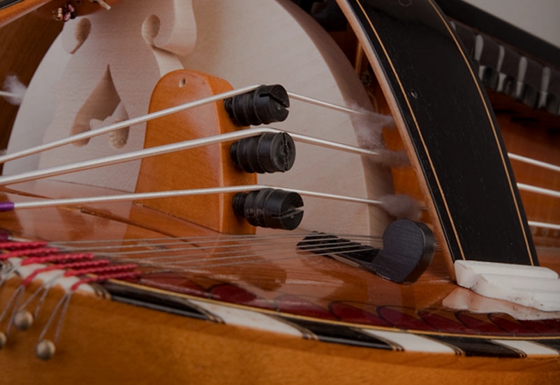
To explain the concept here is a picture of a Boudet hurdy-gurdy :
Here are the screw before doing anything (Hexagon socket countersunk head screws)

I’m shaping them … with a file !

The screws once finished :

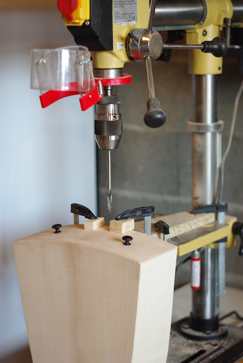
A newcomer has arrived in the workshop : a beautiful drill press (almost essential for what’s next) that you can see on the next picture !

To continue with the hurdy-gurdy, I drill the holes where the strap buttons (so you can strap a belt to hold the gurdy). First on the back side (on the pegbox side) :

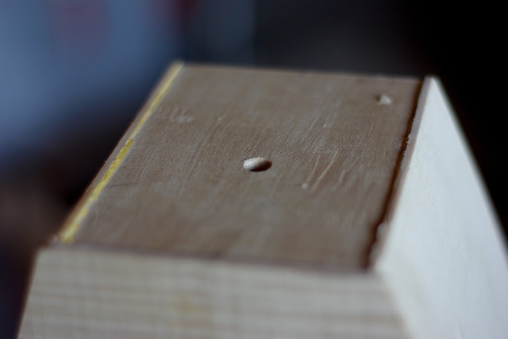
And then on the front side (the crank side)

The wood has splintered a bit even I used a backup plank on the other side, well it wasn’t serious !

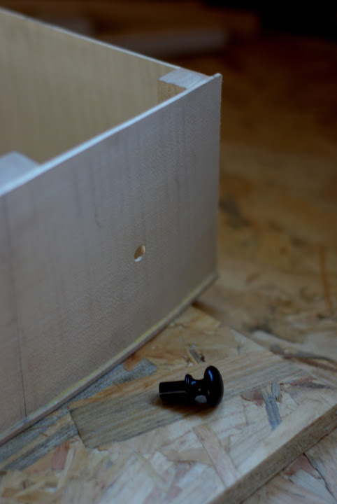
Here is one of the strap button :
On the front side (the crank side) the buttons are glued directly on the side. You have to glue a back-up piece on the inside. Here I’m adjusting the back-up piece with some sanding paper to make it fit perfectly with the side :

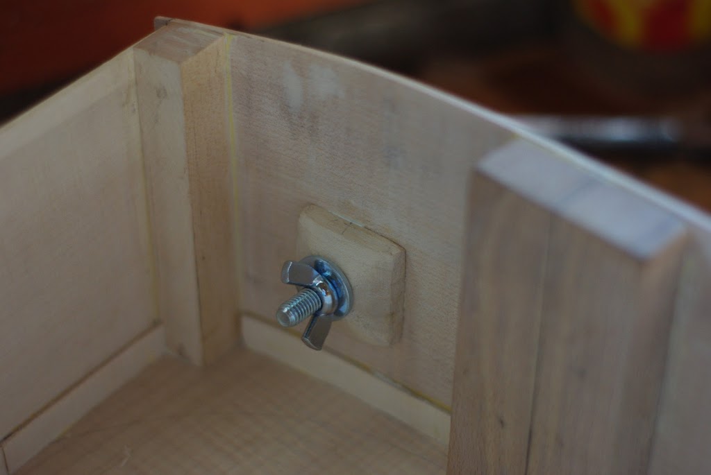
The back-up pieces are then glued and tighten using a bolt and a wingnut (and small wood protections) :


Once the back-up pieces are glued, I was able to glue the buttons.
I then drilled the hole on the crank side where the wheel axis will go through :

I also drilled the support bars (but I forgot to take pictures) !
I mounted the wheel on its axis (It was very hard to get something perpendicular, I will have to make some adjustments)

Here is the gurdy with the support bars and the wheel and its axis (but the support bars are not glued) :

I glued the support bars and tighten them with screws !

That’s all ! Next step will be to fasten the axis and to glued the upper linings before I can put the soundtable !
See you